Your Dell computer system supports a variety of internal options that expand system capabilities. This chapter prepares you to install options inside the computer. It describes how to remove and replace the computer cover and expansion-card cage, as well as rotate the power supply away from the system board. It also familiarizes you with the internal components you may handle if you install Dell hardware options.
To make working inside your computer easier, make sure you have adequate lighting and a clean work space. If you temporarily disconnect cables or remove expansion cards, note the position of the connectors and slots so that you can reassemble the system correctly.
You will use the information in this section every time you install a hardware option inside your computer. Read this section carefully, because the information is not repeated in detail elsewhere in this guide.
Working inside your computer is safe—if you observe the following precautions.
 |
CAUTION FOR YOUR PERSONAL SAFETY AND PROTECTION OF YOUR EQUIPMENT |
Before starting to work on your computer, perform the following steps in the sequence indicated:
While you work, periodically touch an unpainted metal surface on the computer chassis to dissipate any static electricity that might harm internal components. Also avoid touching components or contacts on a card and avoid touching pins on a chip.
In addition, Dell recommends that you periodically review the safety instructions in your System Information Guide.
When you remove an option from its shipping carton, you may find it wrapped in antistatic packing material designed to protect it from electrostatic damage. Do not remove the packing material until you are ready to install the option.
Use the following procedure to remove the computer cover:
|
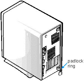
Face the back of the computer and slide the upper half of the padlock ring to the left to unlock the cover release mechanism.
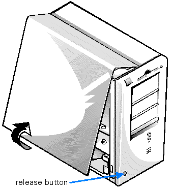
Face the left side cover and press the left-cover release button that is located at the bottom-left corner of the front panel (see Figure 2).
Lift the bottom of the cover, allowing it to pivot up toward you.
Disengage the tabs that secure the cover to the top of the chassis, and lift the cover away.
Figure 2. Removing the Computer Cover
|
Use the following procedure to replace the computer cover:
Face the left side of the computer and hold the cover at a slight angle as shown in Figure 3. While aligning the top of the cover with the top of the chassis, insert the hooks on the cover into the recessed slots on the computer chassis.
Pivot the cover down toward the bottom of the chassis and into position. With both hands, press against the bottom edge of the cover to make sure that the securing hooks at the bottom of the cover click into place.
Slide the two halves of the padlock ring together to lock the cover release mechanism.
 |
NOTE: The computer should be placed
fully on a flat surface. It is difficult to align the cover if the front to the computer
is hanging over the edge of table.
|
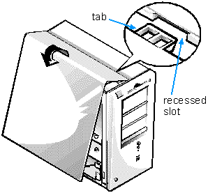
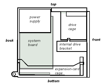
Figure 4 shows a side view of your computer to help orient you when installing hardware options. Unless otherwise specified, locations or directions relative to the computer are as shown.
|
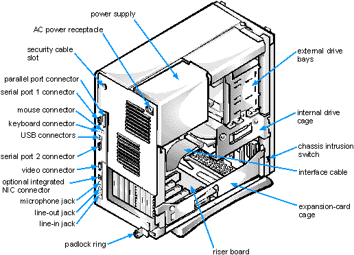
Figure 5 shows your computer with its cover removed. Refer to this illustration to locate interior features and components discussed in this guide.
When you look inside your computer, note the DC power cables coming from the power supply. These cables supply power to the system board; to internal diskette drives, hard-disk drives, and tape drives; and to certain expansion cards that connect to external peripherals.
The flat ribbon cable in Figure 5 is typical of the interface cables for internal drives. An interface cable connects a drive to a connector on the system board or on an expansion card.
The system board—the large printed circuit board mounted vertically inside the chassis—holds the computer's control circuitry and other electronic components. Some hardware options are installed directly onto the system board. The riser board at the bottom of the chassis contains the expansion-card connectors.
During an installation procedure, you may be required to change a jumper setting on the system board and/or a jumper setting on an expansion card or on a drive. Jumpers provide a convenient and reversible way of reconfiguring the circuitry on a printed circuit board. For more information, see "Jumpers."
|
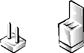
Jumpers are small blocks on a circuit board with two or more pins emerging from them. Plastic plugs containing a wire fit down over the pins. The wire connects the pins and creates a circuit.
To change a jumper setting, pull the plug off its pin(s) and carefully fit it down onto the pin(s) indicated.
|
| NOTICE: Make sure your system is turned off before you change a jumper setting. Otherwise, damage to your system or unpredictable results may occur. |
A jumper is referred to as open or unjumpered when the plug is pushed down over only one pin or if there is no plug at all. When the plug is pushed down over two pins, the jumper is referred to as jumpered. In some documents, the jumper setting may be shown in text as two numbers, such as 1-2. The number 1 is printed on the circuit board so that you can identify each pin number based on the location of pin 1.
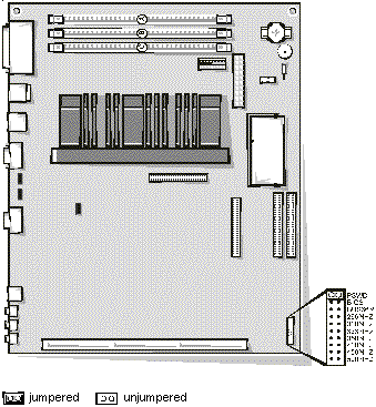
Figure 6 shows the location and default settings of the jumper blocks on your system board. See Table 1 for the designations, default settings, and functions of your system's jumpers.
Figure 6. System Board Jumpers
|
Table 1. System-Board Jumper Settings
| Jumper | Setting | Description |
|---|---|---|
| PSWD |  |
Password features are enabled. |
 |
Password features are disabled. | |
| BIOS |  |
Reserved (do not change). |
| BUS66M | |
Reserved (do not change). |
| 266MHZ* | |
Reserved (do not change). |
| 300MHZ* | |
Reserved (do not change). |
| 333MHZ* | |
Reserved (do not change). |
| 350MHZ* | |
Reserved (do not change). |
| 400MHZ* | |
Reserved (do not change). |
| 450MHZ* | |
Reserved (do not change). |
| 500MHZ* | |
Reserved (do not change). |
| * | The correct microprocessor speed is automatically detected and set by the system. Do not change the settings of these jumpers. |
| The system can operate with a microprocessor speed up to 600 MHz. |
| NOTE: For the full name of an abbreviation or acronym used in this table, see the Glossary in your online System User's Guide. |
 |
jumpered |  |
unjumpered |
Table 2 lists the labels for connectors and sockets on your system board and riser board, and it gives a brief description of their functions.
Table 2. System Board and Riser Board Connectors and Sockets
| Connector or Socket | Description |
|---|---|
| AMC | ATI multimedia channel |
| BATTERY | Battery socket |
| CD_IN | CD-ROM audio interface connector |
| DIMM_x | DIMM socket |
| DSKT | Diskette/tape drive interface connector |
| ENET | NIC connector (optional) |
| FAN | Microprocessor fan connector |
| HDLED | Hard-disk drive LED connector (on riser board) |
| IDEn | EIDE interface connector |
| INTRUSION | Chassis intrusion switch connector |
| ISAn* | ISA expansion-card connector (on riser board) |
| KYBD | Keyboard connector |
| LINE-IN | Audio line-in jack |
| LINE-OUT | Audio line-out jack (amplified source) |
| MIC | Microphone jack |
| MONITOR | Video connector |
| MOUSE | Mouse connector |
| P1 | Wakeup On LAN power connector (on riser board) |
| PANEL | Control panel connector |
| PARALLEL | Parallel port connector; sometimes referred to as LPT1 |
| PCIn* | PCI expansion-card connector (on riser board) |
| POWER_1 | Main power input connector |
| POWER_2 | 3.3-V power input connector |
| RISER | Riser board connector |
| SERIALn | Serial port connectors |
| SLOT1 | Pentium II processor SEC cartridge connector |
| TAPI | Telephony connector |
| USB | USB connectors |
| VIDEO_UPGRADE | Video-memory upgrade socket |
| * | For information on ISA and PCI connectors, see "Expansion Cards." |
| NOTE: For the full name of an abbreviation or acronym used in this table, see the Glossary in your online System User's Guide. |
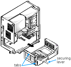
Your Dell computer has a removable expansion-card cage, which greatly simplifies many installation procedures by allowing you to remove the riser board and all installed expansion cards in a single step.
Use the following procedure to remove the expansion-card cage:
|
CAUTION: Before you remove the computer cover, see "Safety First — For You and Your Computer." |
Figure 7. Removing the Expansion-Card Cage
|
Use the following procedure to replace the expansion-card cage:
|
NOTE: If Enabled, the Chassis Intrusion option will cause the following message to be displayed at the next system
start-up: ALERT! Cover was previously removed. |
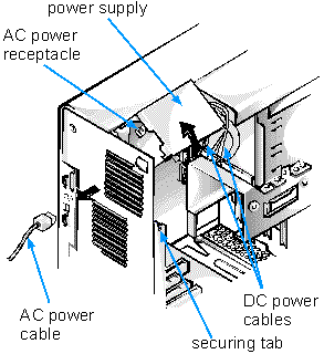
To access some components on the system board, you may have to rotate the system power supply out of the way. Use the following procedure to rotate the power supply:
|
CAUTION: Before you remove the computer cover, see "Safety First — For You and Your Computer." |
|
Figure 8. Rotating the Power Supply