Back to Contents Page
Hard-Disk Drives: Dell™ OptiPlex™ GX100 System User's Guide
The small form-factor and low-profile chassis support a single
enhanced integrated drive electronics (EIDE) hard-disk drive in the hard-disk drive bay.
In the mini tower chassis, you can install up to two EIDE drives (one of which must be 1
inch high or less) in the hard-disk drive bracket below the drive cage. The first EIDE
drive is installed in the 1-inch (lower) drive bay labeled "HD1"; a second drive
is installed in the 1.6-inch bay labeled "HD2."
All EIDE devices require that you
configure the cable select setting, which assigns master and slave status to
devices according to their position on the interface cable. You usually
configure a drive for cable select by setting a jumper or switch, depending on
the drive. Refer to the drive documentation in your upgrade kit for information
on configuring devices for the cable select setting. When you connect two EIDE
devices to a single EIDE interface cable and configure them for the cable select
setting, the device attached to the last connector on the interface cable is the
master or boot device (drive 0) and the device attached to the middle connector
on the interface cable is the slave device (drive 1).
With the two EIDE interface connectors
on the system board, your system supports up to four EIDE devices in the mini
tower chassis; the small-form-factor and low-profile chassis support up to two
EIDE devices. EIDE hard-disk drives should be connected to the EIDE interface
connector labeled "IDE1." (Always connect EIDE tape drives and CD-ROM drives to
the EIDE interface connector labeled "IDE2.")
To install an EIDE hard-disk drive in a small-form-factor chassis,
perform the following steps:

|
CAUTION: To avoid the possibility
of electric shock, turn off the computer and any peripherals, disconnect them
from electrical outlets, and then wait at least 15 seconds before you remove
the computer cover. Also, before you install a drive, see the other precautions
in "Safety First — For You and Your
Computer."
|
- If you are replacing a hard-disk drive that contains data
you want to keep, be sure to make a backup of your files before you continue this
procedure.
- Prepare the drive for installation.
NOTICE: Ground yourself by touching an unpainted metal surface on the
back of the computer.
NOTICE: When you unpack the drive, do not set it on a hard surface, which may
damage the drive. Instead, set the drive on a surface, such as a foam pad, that will
sufficiently cushion it.
Check the documentation for the drive to verify that it is configured for your computer
system.
- Remove the computer cover as instructed
in "Removing
and Replacing the Computer Cover."
- Remove the drive shelf from the chassis.
- Disconnect the power and interface cables from the diskette drive and CD-ROM drive (if
any).
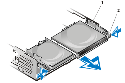
- Press inward on the two drive shelf release tabs, and pull the shelf forward and out of
the chassis (see Figure 1).
Figure 1.
Removing the Drive Shelf From the Small-Form-Factor Chassis
|
| 1
|
Drive shelf
|
| 2
|
Release tabs (2)
|
|
- Remove the drive bracket from the chassis.
- If a drive is already installed in the bracket, disconnect the power
and interface cables from the back of the drive.
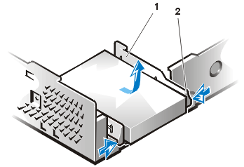
- Squeeze the tabs on each side of the drive bracket, and slide it
forward about one inch (see Figure 2).
Figure 2. Removing
the Hard-Disk Drive Bracket From the Small-Form-Factor Chassis
|
| 1
|
Drive bracket
|
| 2
|
Release tabs (2)
|
|
- Lift the drive bracket away from the chassis.
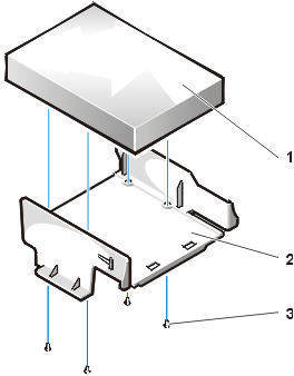
- If a drive is already installed in the bracket, remove the four screws securing the
drive to the bottom of the bracket (see Figure 3).
Figure 3.
Removing a Hard-Disk Drive From the Hard-Disk Drive Bracket
|
| 1
|
Drive
|
| 2
|
Drive bracket
|
| 3
|
Screws (4)
|
|
- Secure the new drive to the drive bracket with four screws (see Figure 3).
- Reinstall the hard-disk drive bracket in the chassis.
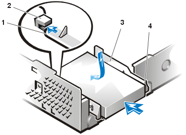
- Place the bracket so that the release tabs extend about one inch past
the front of the chassis, and align the tabs on the bottom of the bracket with the hooks
on the chassis floor.
- Then slide the bracket toward the back of the
chassis until the tabs snap under the hooks (see Figure 4). The bracket
release tabs should also snap into the front of the chassis.
Figure 4.
Reinstalling the Hard-Disk Drive Bracket in the Small-Form-Factor Chassis
|
| 1
|
Tabs on bottom of drive bracket
|
| 2
|
Hooks on chassis floor
|
| 3
|
Drive bracket
|
| 4
|
Release tabs (2)
|
|
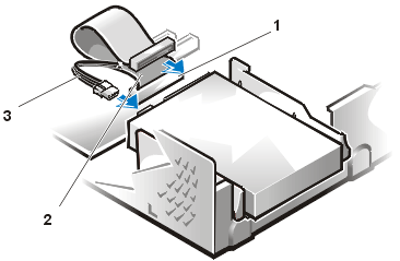
- Connect a power cable to the power input connector on the back of the drive,
and connect an EIDE cable to the interface connector on the back of the drive
(see Figure 5).
Check all connectors to be certain that they are properly cabled and firmly seated.
NOTICE: You must match the colored strip on the EIDE cable
with pin 1 on the drive's interface connector to avoid possible damage to your system.
Figure 5. Attaching
Hard-Disk Drive Cables in the Small-Form-Factor Chassis
|
| 1
|
IDE1 connector
|
| 2
|
EIDE cable
|
| 3
|
Power cable
|
|
- If it is not already connected, connect the blue end of the EIDE cable to the IDE1
connector on the system board.
NOTICE: You must match the colored strip on the
EIDE cable with pin 1 on the IDE1 connector to avoid possible damage to your system.
To locate the IDE1 connector on the system board,
see Figure 7 in "Inside Your
Computer."
- Replace the computer cover. Then reconnect
your computer and peripherals to their electrical outlets, and turn them on.
- Insert a bootable system diskette into drive A.
- Turn on the computer system.
- Enter System Setup, and
update Primary Drive 0.
After
you update the System Setup settings, reboot the system.
- Partition and logically format your drive before proceeding to the next step.
See the documentation for your operating system for instructions.
- Test the hard-disk drive by running the Dell Diagnostics.
- If the drive you just installed is the primary drive, install your operating system on
the hard-disk drive.
For instructions, refer to the documentation that came with your
operating system.
To install an EIDE hard-disk drive in a low-profile chassis, perform
the following steps:
|
|
CAUTION: To avoid the possibility
of electric shock, turn off the computer and any peripherals, disconnect them
from electrical outlets, and then wait at least 15 seconds before you remove
the computer cover. Also, before you install a drive, see the other precautions
in "Safety First — For You and Your
Computer."
|
- If you are replacing a hard-disk drive that contains data you want to keep, be sure to
make a backup of your files before you begin this procedure.
- Prepare the drive for installation.
NOTICE: Ground yourself by touching an
unpainted metal surface on the back of the computer.
NOTICE: When you unpack the drive, do not set it on a hard surface, which may
damage the drive. Instead, set the drive on a surface, such as a foam pad, that will
sufficiently cushion it.
Check the documentation for the drive to verify that it is configured for your computer
system.
- Remove the computer cover.
- Remove the drive bracket from the chassis.
- If a hard-disk drive is already installed in the drive bracket, disconnect the DC power
cable and EIDE cable from the drive.
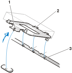
- Remove the screw securing the hard-disk drive bracket to the drive cage in the chassis.
- Grasp the bracket, and rotate it outward from the chassis until the sliding tab clears
the slide rail on the drive cage (see Figure 6). Lift the bracket up slightly to free its
hinge tabs from the chassis slots.
Figure 6. Removing
the Hard-Disk Drive Bracket
|
| 1
|
Captive screw
|
| 2
|
Tabs on back of drive bracket (2)
|
| 3
|
Slots in chassis floor divider (3)
|
|
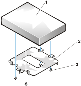
- Slide the drive into the chosen bay of the bracket, orienting the drive so that the
connectors on the back of the drive will face the back of the chassis when you reinstall
the bracket (see
Figure 7).
- Align the four screw holes of the drive and bracket. Insert and tighten the screws that
came with your upgrade kit.
- If you are installing a drive in the 1.6-inch bay, use the four screw holes in the side
of the bracket (see Figure 7).
- If you are installing a drive in the 1-inch bay, use the four screw
holes in the bottom of the bracket.
Figure
7. Inserting a 1.6-Inch Hard-Disk Drive in the Bracket
|
| 1
|
Hard-disk drive
|
| 2
|
Bracket
|
| 3
|
Screws (4)
|
|
- Reinstall the hard-disk drive bracket in the chassis.
- Insert the bracket's hinge tabs into the chassis slots so that the tabs hook over the
slots.
- Then rotate the bracket toward the drive cage, and fit the bracket's
sliding tab on the drive-cage slide rail.
- Slide the bracket into place, and reinstall the screw you removed in
step 4.
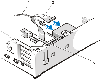
- Connect a power cable to the power input connector on the back of the
drive (see Figure 8).
Check all connectors to
be certain that they are properly cabled and firmly seated.
- Connect one of the device connectors on the EIDE cable to the 40-pin
interface connector on the back of the hard-disk drive.
NOTICE: You must match
the colored strip on the EIDE cable with pin 1 on the drive's interface connector to avoid
possible damage to your system.
Figure 8. Attaching
Hard-Disk Drive Cables
|
| 1
|
Power cable
|
| 2
|
EIDE cable
|
| 3
|
IDE1 connector
|
|
- If it is not already connected, connect the other end of the EIDE cable to the IDE1
connector on the system board.
NOTICE: You must match the colored strip on the
EIDE cable with pin 1 on the IDE1 connector to avoid possible damage to your system.
To locate the IDE1 connector on the system board,
see Figure 7 in "Inside Your
Computer."
- Replace the computer cover. Then reconnect your computer and
peripherals to their electrical outlets, and turn them on.
- If the drive you just installed is the primary drive,
insert a bootable system diskette into drive A.
- Turn on the computer system.
- Enter System Setup, and update the
appropriate Primary Drive
option (0 or 1).
- After you update the System Setup settings, reboot the system.
- Partition and logically format your drive before you proceed to the next step.
See the documentation for your operating system for instructions.
- Test the hard-disk drive by running the Dell Diagnostics.
- If the drive you just installed is the primary drive, install your operating system on
the hard-disk drive.
For instructions, refer to the documentation that came with your
operating system.
To install an EIDE hard-disk drive in a mini tower chassis, perform
the following steps:
|
|
CAUTION: To avoid the possibility
of electric shock, turn off the computer and any peripherals, disconnect them
from electrical outlets, and then wait at least 15 seconds before you remove
the computer cover. Also, before you install a drive, see the other precautions
in "Safety First — For You and Your
Computer."
|
- If you are replacing a hard-disk drive that contains data you want to
keep, be sure to make a backup of your files before you continue this procedure.
- Prepare the drive for installation.
NOTICE: To avoid
possibly damaging the drive by electromagnetic static (EMS), ground yourself by touching
an unpainted metal surface on the back of the computer.
NOTICE: When you unpack the drive, do not set it on a hard
surface, which may damage the drive. Instead, set the drive on a surface, such as a foam
pad, that will sufficiently cushion it.
Check the documentation for the drive to verify that it is
configured for your computer system.
- Remove the computer cover.
- Remove the drive bracket from the chassis.
- If a hard-disk drive is already installed in the
drive bracket, disconnect the DC power
cable and EIDE cable from the drive.
- Remove the screw securing the hard-disk drive
bracket to the drive cage in the chassis.
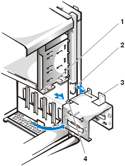
- Grasp the bracket, and rotate it outward from
the chassis until the sliding tab clears the slide rail on the drive
cage (see Figure 9). Lift the bracket up slightly to free its hinge
tabs from the chassis slots.
Figure 9.
Removing the Hard-Disk Drive Bracket
|
| 1
|
Drive-cage slide rail
|
| 2
|
Chassis slots
|
| 3
|
Hinge tabs
|
| 4
|
Sliding tab
|
|
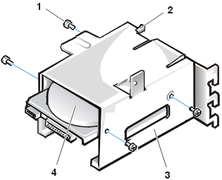
- Slide the drive into the chosen bay of the bracket, orienting the drive so that the
connectors on the back of the drive will face the back of the chassis when you reinstall
the bracket (see Figure 10).
- Align the four screw holes of the drive and bracket. Insert and tighten the screws that
came with your upgrade kit.
- If you are installing a drive in the 1.6-inch bay, use the four screw holes in the side
of the bracket (see Figure 10).
- If you are installing a drive in the 1-inch bay, use the four screw holes in the bottom
of the bracket.
Figure 10. Inserting a
1.6-Inch Hard-Disk Drive in the Bracket
|
| 1
|
Screws (4)
|
| 2
|
Sliding tab
|
| 3
|
Drive bracket
|
| 4
|
1.6-inch drive
|
|
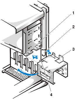
- Reinstall the hard-disk drive bracket in the chassis
(see Figure 11).
- Insert the bracket's hinge tabs into the chassis slots so that the tabs hook over the
slots.
- Then rotate the bracket toward the drive cage, and fit the bracket's sliding tab on the
drive-cage slide rail.
- Slide the bracket into place, and reinstall the screw you removed in step 4.
Figure 11. Inserting the
Drive Bracket in the Chassis
|
| 1
|
Drive-cage slide rail
|
| 2
|
Chassis slots
|
| 3
|
Hinge tabs
|
| 4
|
Sliding tabs
|
|
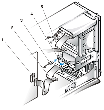
- Connect a power cable to the power input connector on the back of the
drive (see Figure 12).
Check all connectors to be certain
that they are properly cabled and firmly seated.
- Connect one of the device connectors on the EIDE cable to the 40-pin interface connector
on the back of the hard-disk drive.
NOTICE: You must match the colored strip on
the EIDE cable with pin 1 on the drive's interface connector to avoid possible damage to
your system.

|
NOTE: On systems with hard-disk drives
larger than 2 GB, create a primary partition of 2 GB and divide the remaining capacity
into partitions of 2 GB or less. For example, a system with a 2.5-GB hard-disk drive would
have a primary partition of 2 GB (drive C) and a second partition of 500 MB (drive D).
Hard-disk drives must be partitioned this way because MS-DOS-based operating systems
(including Windows NT, when using a file allocation table [FAT] 16 file system) do not
support drive partitions larger than 2 GB.
|
Figure 12.
Attaching Hard-Disk Drive Cables
|
| 1
|
Interface connector
|
| 2
|
Interface cable
|
| 3
|
Power cable
|
| 4
|
Power input connector on drive
|
| 5
|
Interface connector on drive
|
|
- If it is not already connected, connect the other end of the
EIDE cable to the IDE1 connector on the system board.
NOTICE: You must match the colored strip on the EIDE cable with pin 1
on the IDE1 connector to avoid possible damage to your system.
To locate the IDE1 connector, see Figure
7 in "Inside Your Computer."
- Replace the computer cover.
Then reconnect your computer and peripherals to their electrical outlets, and turn them
on.
- If the drive you just installed is the primary drive, insert a
bootable system diskette into drive A.
- Turn on the computer system.
- Enter System Setup, and update the appropriate Primary Drive
option (0 or 1).
- After you update the System Setup settings, reboot the system.
- Partition and logically format your drive before you proceed to the next step.
See the documentation for your operating system for instructions.
- Test the hard-disk drive by running the Dell Diagnostics.
- If the drive you just installed is the primary drive, install your
operating system on the hard-disk drive.
For instructions, refer to the documentation
that came with your operating system.
Back to Contents Page
